|
Most Advanced Bass-Reflex
Loudspeaker System MCAP-CR Multiple-Chamber
Aligned in Parallel Cavity Resonator
A True Multiple Degree of Freedom Cavity Resonator Technical Information for Loudspeaker Designers |
| Items | Link |
| Theory of MCAP-CR | Calculation Details (PDF in English) |
| Basic concept of MCAP-CR | Concept of MCAP Cavity Resonator (PDF in English) |
| Simplified calclation approach to estomate characteristic frequencies without eigen value theory | Simpler Method to Estimate Characteristic Frequencies of MCAP Cavity Resonator (PDF in English) |
| Calculation tool to estimate characteristic frequencies based on above simplification approach | Simplified Calculation Sheet (Microsoft Excel file) |
| New! Suggested Cabinet for 4.5" - 5" drivers TR120b. |
1. Overview
MCAP-CR is an extended application of bass-reflex speaker enclosure. MCAP-CR stands for Multiple-Chamber Aligned in Parallel Cavity Resonator.
MCAP-CR is true multiple degree of freedom cavity resonator application. An MCAP-CR generates very low frequency sound pressure in considerablly high level. You may design MCAP-CR to considerably small size. You will find applications here.
MCAP-CR is developed by myself and patent application was submitted to Japan Patent Office in March 2007, yet there is no limitation to use the idea for non-commercial personal use.
You may flexiblly design your own MCAP enclosure by yourself. MCAP-CR is somewhat more complicated than simple bass-reflex enclosure, but easier to assemble than back-loaded horn systems.
You may ask me any questions, if you have interested in this system and want to know more.
My email address is "mcapspeakers @ gmail.com". Please remove spaces of both sides of @ from the email address. These spaces are intended to protect from SPAM.
Sincerely,
Shigeru Suzuki
2. Advantages of MCAP-CR
MCAP-CR has multiple characteristic frequency. This realizes flat response over the low frequency range.
Characteristics below may be stressed:
(Characterstics of Sound)
- Frequency of lowest end is generally lower than other enclosure types like back-loaded horn or bass-reflex systems, if total size is equivalent.
- Sond character is similar to bass-reflex system, rather
than back-loaded horn or pipe resonator systems.
(Characteristics of Structure)
- There are chambers in the enclosure.
- There are separation walls in the enclosure. These walls make the enclosure stiffer.
- Speaker driver is installed in the main chamber and sub-chambers are connected to main chamber by inter-chamber ducts.
- At least one of the subchambers have open-air duct.
3. Principle of MCAP-CR
We may note that MCAP-CR is an application of bass-reflex enclosure. We need to understand how bass-reflex enclosure works.
Principle of Bass-Reflex Enclosure
Fig.1 shows equivalent model of Bass-Reflex enclosure or cavity resonator. This is just a simple vibration model. You may have learned in high school or college. Simple vibration generally has single characteristic frequency.
Fig.1 Equivalent Model of
Bass-Reflex Enclosure
Characteristic frequency of this model is expressed as:
fD = 1/2π*(k/m)1/2
where,fD :
Characteristic frequency of duct mass
k : Stiffness
of air in the chamber for the duct
m : Mass of air
involved in the duct
Refer to detailed calculation document here.
Fig.2 shows double-bass-reflex enclosure. Please note that double-bass-reflex enclosure has two masses in the system.
Fig.2 Equivalent Model of
Double-Bass-Reflex Enclosure
Fig.2 shows equivalent model of double-bass-reflex enclosure. Double-bass-reflex model is a coupled oscillation model. Calculating characteristic frequencies of this two degree of freedom oscillation model is not difficult. We do not need computer programme to solve this model. Refer to Appendix-1 of MCAP006E for more details.
Double-bass-reflex model can be extended to triple, quadraple, and even more multiple-bass-reflex models. Fig.3 shows quadraple bass-reflex enclosure model.
Fig.3 Equivalent Model of
Quadraple-Bass-Reflex Enclosure
Multiple-Bass-Reflex Model to MCAP-CR Model
MCAP-CR is different from Multiple-Bass-Reflex noted above. MCAP-CR consists of a main chamber and sub-chambers. Sub-chambers are connected in parallel. This is the main difference from Multiple-Bass-Reflex enclosure.
Fig.4 shows schematics of MCAP-CR model. This schematics has four sub-chambers as an example. Number of sub-chambers is unlimited.
Fig. 4 Schematics of MCAP-CR
In this case, number of ducts are eight, so number of characteristic frequencies is up to eight. We may design this cavity resonator to have unique characteristic frequencies, so, in general. Number of characteristic frequency is same as number of ducts.
Please refer to MCAP001E for more details.
You may read simplified calculation approach explained here.
4. Application Sample
You will find an application example of MCAP-CR below (Fig.5). This example is easy to understand the structure of standard MCAP-CR.
Four chambers are alligned vertically in this example. From top to bottom, 1st chamber is #1 subcember, 2nd one is main chamber, 3rd one is #2 subchamber and last one is #3 subchamber.
Each subchamber is connected to main chamber through internal duct, and each subchamber has external duct exposed to outside, while main chamber is not directly exposed to outside. This structure is important feature of standard MCAP-CR.
Fig. 5 An application example of MCAP-CR
As stated above, there are three sub-chambers and six ducts, and it configures six degree of freedom cavity resonator. This was designed for 8" driver Fostex FE206E, but later modified for Feastrex 5"driver.
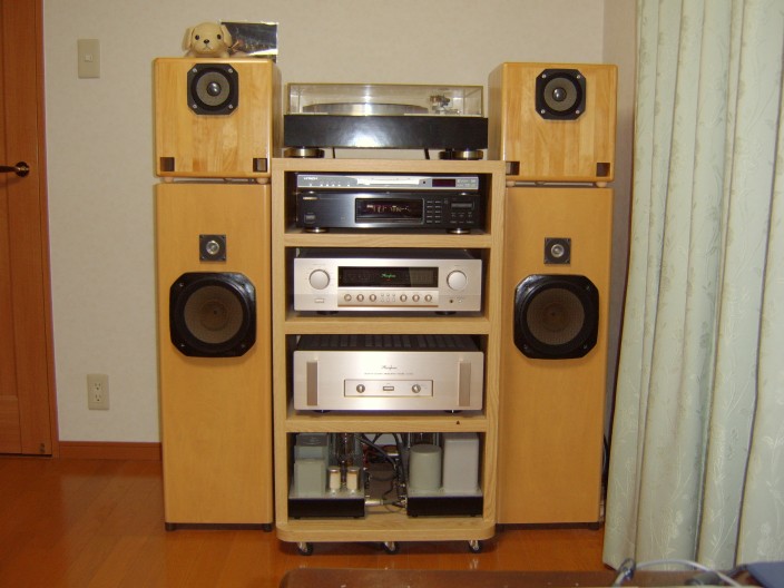
Applications of MCAP-CRs
This picture shows two applications of MCAP-CRs, respectively, 4.5" driver and 8" drivers. These application seems standard bass-reflex or closed cabinets.
Slit duct is not at all recommended. Slit duct will cause much calculation error and users may not expect designed result.
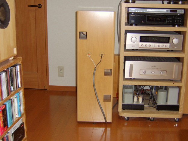
Rear Side of MCAP-CR 8" application
This is rear side of 8" MCAP-CR system. You will see three ducts in the rear side. Three more ducts are hidden in inside the enclosure as shown in Fig.5.
You will ask "where is the woofer?" if you hear the soud of MCAP-CRs. You will not believe that these are full-range driver systems until you hear the sound. You should try MCAP-CR if you do not believe this fact.
5. Determining Principal Parameters of MCAP-CR
There have been some questions about determining design parameters of MCAP-CR.
There are some application reports in this site and they will be helpful for ones who want to develop ones' own systems. On the other hand, it may be difficult for most people to design own systems just using information in this site.
Here is some information about determining design parameters of MCAP-CR. Most information has not been proven yet, but based on my experience and engineering sense. This guideline will be updated everytime when I find new facts.
Here are reference materials:
Simplified Method to
Estimate Characteristic Frequencies of MCAP-CR
Simplified Calculation Sheet (Microsoft Excel file)
Simplified Calculation Sheet (Microsoft Excel file)
Principal parameters of MCAP-CR are defined in the following table.
Principal
Parameters of MCAP-CR
| item# | Parameter | Definition or Meaning | Note |
| 1 | n | Number of Sub-chambers | |
| 2 | V0 | Volume of main chamber | |
| 3 | V1 - Vn | Volume of sub-chamber | |
| 4 | a1 - an | Cross sectional area of inter-chamber duct | Cross section of duct should be circular. It may be
square if circular pipe is not available. Slit duct is not at all recommended. Slit duct will cause much calculation error and users may not expect designed result. |
| 5 | an+1 - a2n | Cross sectional area of open-air duct | Cross section of duct should be circular. It may be
square if circular pipe is not available. Slit duct is not at all recommended. Slit duct will cause much calculation error and users may not expect designed result. |
| 6 | l1 - l2n | Length of duct | |
| 7 | f1 - fn | Characteristic frequency of inter-chamber duct | These are calculated values based on item# 1 - 5 |
| 8 | fn+1 - f2n | Characteristic frequency of open-air duct | These are calculated values based on item# 1 - 5 f2n < f2n-1 < ...< fn+1 |
Suggested range of principal parameters is in the following table.
Suggested Paramater Range of MCAP-CR
| item# | Parameter | Suggested Range | Note |
| 1 | n | Number of Sub-chambers | 3 or more is recommended for all drivers. 4 or more is
recommended for 4" or smaller drivers. Here are exceptions: Lowest characteristic frequency is set larger than 50Hz for 5" or larger driver. Lowest characteristic frequency is set larger than 60Hz for 4.5" or smaller driver. |
| 2 | V0 | Volume of main chamber |
|
| 3 | V1 - Vn | Volume of sub-chamber | 0.5V0 < V1 ,..., Vn < 2V0 |
| 4 | a1 - an | Cross sectional area of inter-chamber duct | 0.5a0 < Arithmetic sum of (a1
,..., an) < 1a0 Same cross-sectional area for all inter-chamber duct is recommended |
| 5 | an+1 - a2n | Cross sectional area of open-air duct | 0.3a0 < Arithmetic sum of (an+1
,..., a2n) < 0.6a0 Same cross-sectional area for all all open-air duct is recommended |
| 6 | f1 - fn | Characteristic frequency of inter-chamber duct | See frequency response curve of the driver and determine. |
| 7 | l1 - l2n | Length of duct | These values are determined to suffice characteristic frequency spec. |
| 8 | fn+1 - f2n | f2n : 20Hz - 30Hz for 8" or bigger drivers 25Hz - 30Hz for 6.5" drivers 30Hz - 40Hz for 5" drivers 40Hz - 70Hz for 4" or smaller drivers fn+1 : 50Hz - 100Hz |
These are just suggested range. One does not have to
insist on this range. It should be based on one's preferred music
sources:
|
Note this is just a guideline and one can set the specification outside of this range. This guideline is not rigid constraint.
Success is not promissed, even though keeping this guideline.
Enjoy your own design!